GPU nodes are custom nodes based on a GPU script used to interact with the data handled by Instant Terra.
Creating and editing a GPU custom node
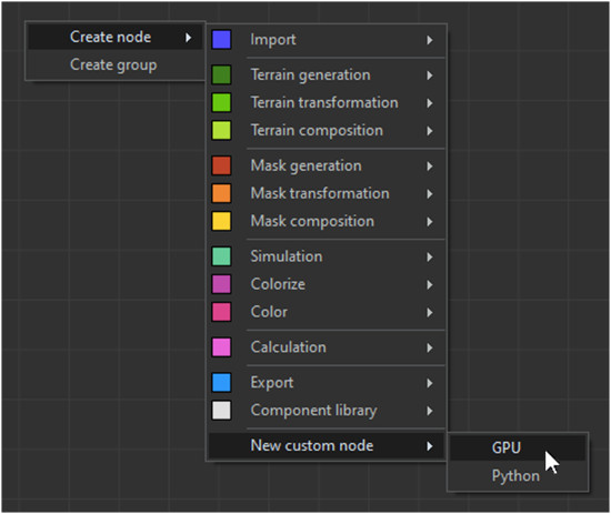
- To create a GPU custom node, select New custom node > GPU in the creation node menu.
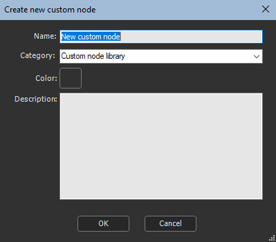
- Specify a name, a category and a color for the node.
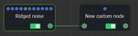
The node is displayed in the graph with the default settings (an input terrain, a parameter, and an output terrain).
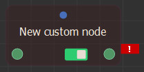
The node appears as invalid as it is not yet
connected to any input terrain. Connect it to any terrain to view
the default GPU node working.
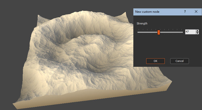
- Select the custom node to display its parameter, named "Strength". Change its value to apply a wave effect.
Editing the node's graph
Right-click the node to show the contextual menu then select Edit custom node.
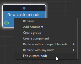
The custom node's graph window opens.
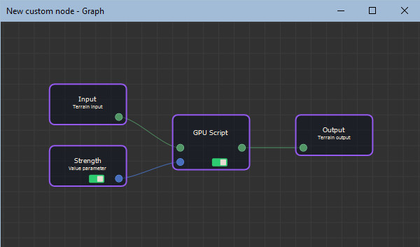
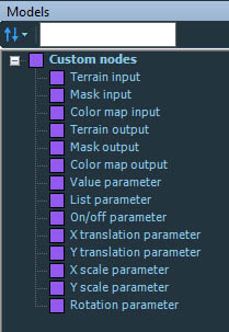
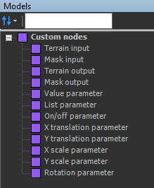
This is where you will define the inputs, outputs and parameter (including manipulators) nodes, and also enter the GPU script.
The GPU script
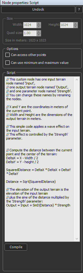
The GPU script node is created from a default sample script. This default custom node has one input terrain, one output terrain, and one parameter: Strength.
Select the GPU script node to open its properties and the script editor.
When the node has no input terrain or mask (the node is a generator), specify the size (width, height, quad size); otherwise, these options are disabled and the values are retrieved from the input terrain / mask and the output grids.
Use C++ comments, starting with //, or use Python comments, starting with #.
Input and output data
Any new node, input, output or parameter triggers a new connector on the GPU Script node.
Inputs and outputs are referenced by the node's name.
- An input can only be used to the right of a = sign.
- An output can only be used to the left of a = sign. It is not possible to write an output then read and reuse it for another output.
The script is run for each vertex.
When several input grids are of different sizes, the size of the first grid is used for the output grids and the other input grids are scaled so their sizes match the first input's grid. A different scale may be applied on X and on Y.
Local variables
Define as many local variables as needed in the script. All local variables are the float type.
Predefined variables
The following predefined variables are available in the script:
- Width: Output grid width, in meters
- Height: Output grid height, in meters
- X: Current vertex's X position, in meters
- Y: Current vertex's Y position, in meters
- QuadSize: Quad size of the output terrain or mask, in meters
For example, for a 2048 x 1024 vertices terrain with a 2 meters quad size, the values of the predefined variables are as follows:
- Width: 4096 (2047 quads x 2 meters)
- Height: 2046 (1023 quads x 2 meters)
- X: 0, 2, 4, 6, ... up to 4096
- Y: 0, 2, 4, 6, ... up to 2046
Functions
The complete list of available functions can be found in the Functions list page.
"Can access other points" option
Select this option if you need to read the values of a vertex that is not the current vertex, inside an input grid.
To read a vertex in an input grid, provide its coordinates as a distance in meters from the current vertex.
Positive distance X:
Negative distance Y:
Positive distance Y:
Vertex right from the current vertex
Vertex up from the current vertex
Vertex down from the current vertex
If a script compiles with this option unchecked, it
will not compile when the option is checked as you need to replace
Input by Input[0,0].
This option may slow down the performance.
Example
Output = Input
// Copy of an input grid without any update, when "Can access other points" option is checked:
Output = Input[0, 0] // Input[0, 0] is the vertex being computed
// Offset of a terrain: 2 meters to the right and 4 meters lower:
Output = Input[-2, -4] // We read the vertex located 2 meters left and 4 meters upper from the vertex being processed.
Limitations
To remain GPU compatible, only vertices located at
a maximum distance of 1023 vertices. are read.
- For a quad size of 1 meter, the maximum distance to read a vertex
is 1023 meters.
- For a quad size of 0.5 meter, the maximum distance to read a
vertex if 1023 x 0.5 = 511.5 meters.
- If the distance is too high, it will be automatically reduced to respect the limitations.
- If the distance goes beyond the input grid boundaries, then the distance will be adjusted to reach the border of the input grid.
"No limit on points to access" option
This option is visible only when "Can access other points" is checked.
When this option is checked, it is possible to access ANY
vertex* in an input terrain or mask. This raises the limitation to
the distance of 1023 vertices from the current vertex.
(*currently limited to 8192 x 8192 vertices)
This option may slow down the performances.
"Can use minimum and maximum values" option
Select this option if you need to use the minimum or maximum values of an input grid.
Use the following functions:
Minimum(InputName)
Maximum(InputName)
This option may slow down the performance.
Compiling the script
Once your script ready, compile it by clicking the Compile button below the text editor. Instant Terra checks the code syntax then runs the script. While running, a Stop button is shown to let you stop the execution of the script.
In case of any error while compiling or running, a message is displayed under the Compile button, with information about the error.