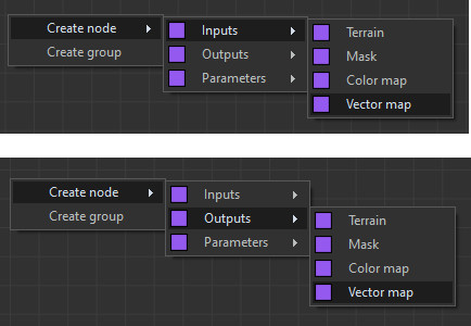
Two nodes exist to read and write a vector map. They have an impact on the images of the GPU input and output nodes. They also have an impact on the images of the GPU scripts color maps.
See Adding inputs and outputs for details on how to edit custom scripts.
Each vector is stored as follows:
- The red channel contains the X component of the vector, from 0 (toward the left) to 0.5 (in the middle, therefore zero component) and 1 (to the right).
- The green channel contains the Y component of the vector.
- The blue channel contains the Z component of the vector.
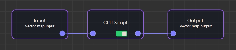
Example
The following is an example of a node that has a vector map input and a vector output map.
Reading the vector:
// Read the vector as a color

 Color v = Input

// Extract each component. Convert from [0, 1] to [-1, 1].

vx = Red (v) * 2 - 1

vy = Green (v) * 2 - 1

vz = Blue (v) * 2 - 1
Writing the vector:
// Convert from [-1, 1] to [0, 1]

r = (vx + 1) / 2

g = (vy + 1) / 2

b = (vz + 1) / 2

// Write to the vector map

Output = Color (r, g, b)
Do not name variables “x” or “y” asthis would conflict with the predefined “x” and “y” variables.
Copyright © 2022 · All Rights Reserved · Wysilab