Adding a Line node
The Line node generates a mask in the form of a straight line segment. The segment is defined by two points, point 1 and point 2, forming the two ends of the segment.
Points 1 and 2 can be moved using the manipulators or their X and Y coordinates can be entered manually in the node properties.
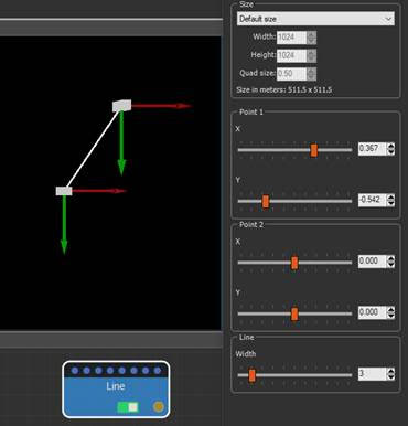
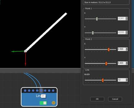
If the coordinate values of a point are constrained
by a value from an optional input connector, the manipulator
associated with these coordinates is not displayed. In the example
below, the coordinate values of point 1 are from another node;
therefore, the manipulator of point 1 no longer appears.

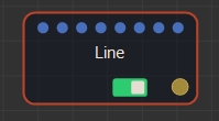
To add an Line node, right-click in the Graph Editor and select Create Node > Mask Generation > Line or press the keyboard shortcut N-L-I (Node Line).
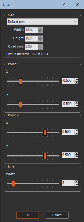
Double click on the node to open its parameters:
Editing a Line node
To edit the Line node:
- Preset: List of existing size presets. Select one from the list to apply the size preset.
- Width: Width of the mask to generate in number of vertices.
- Height: Height of the mask to generate in number of vertices.
- Quad size: Size of the quads of the mask in meters.
- Points 1 and 2: These points define the ends
of the line. Use the sliders to adjust the point's X and Y
coordinates.
The X and Y coordinates of each of the two points are relative to the center of the mask with a value between -1 and +1:- 0 corresponds to the middle in width (X), in height (Y); (0,0) positions the point in the center of the mask.
- -1 and 1 correspond to the minimum and maximum values of the coordinates (limit of the mask); (1,1), (-1,1), (1,-1), and (1,1) position the point in one of the four corners of the mask.
- Line – Width: Adjusts the thickness of the
line from 1 to 20.
Components
The Arc and Line nodes can be used in components to propagate the coordinates of their respective points, allowing the formation of a circuit. An end point of an Arc can be linked to an end point of Line to guarantee a permanently valid link between the different masks. This is used in the Road sample, available in the Help > Samples menu.
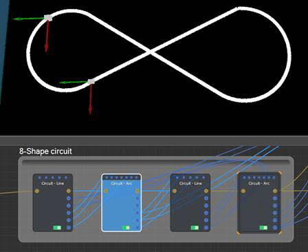
Components can be retrieved from this sample project in the Models window > Mask generation > Circuit - Arc or Circuit - Line, and then right, click and select Export component.
Components can also be retrieved from our site at https://www.wysilab.com/Library/#/.
Parameters
| Parameter | Use |
|---|---|
| Preset | List of existing size presets. |
| Width | Width of the mask to generate in number of vertices. |
| Height | Height of the mask to generate in number of vertices. |
| Quad size | Size of the quads of the mask in meters. |
| Points 1 and 2 | Defines the extremities of the circular Line. |
| Point 3 | Adjusts the radius of curvature of the Line of a circle X and Y. |
| Line - Width | Adjusts the thickness of the line from 1 to 20. |