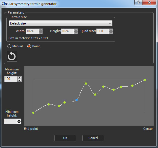
Adding a Circular symmetry node
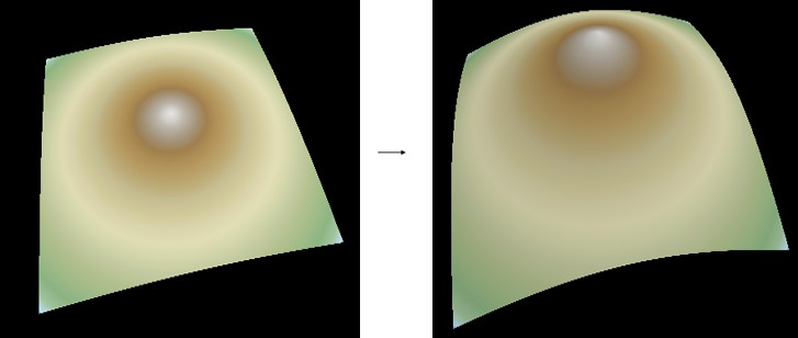
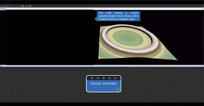
This node creates a circular cone-shaped terrain. The height of the vertices are impacted from the outside to the center, radially. The terrain's profile is edited by a curve.
To add a Circular symmetry node, right-click in the Graph Editor and select Create Node > Terrain Generation > Circular Symmetry.
Double click on the node to open its parameters:
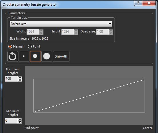
Changing the terrain size
- To change the terrain size, edit the Width and Height fields in number of vertices, or use a preset size from the list.
- To change the quad size, edit the Quad size field in meters.
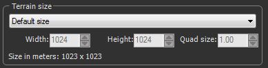
Learn more about terrains and quads.
Setting the minimum and maximum heights
You can set the minimum and maximum height of the vertices to a defined value, represented by a value of 0 and 1, respectively, on the curve.
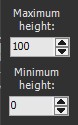
- Minimum height: Determines the minimum height of the vertices whose value on the curve is 0.
- Maximum height: Determines the maximum height of the vertices whose value on the curve is 1.
Editing curve values manually
By default, the Manual curve editing mode is activated.
- Select your cursor size from small, medium, and large.

Using the smallest cursor makes detailed changes to the values; using a larger cursor makes changes to larger areas in the circular symmetry.
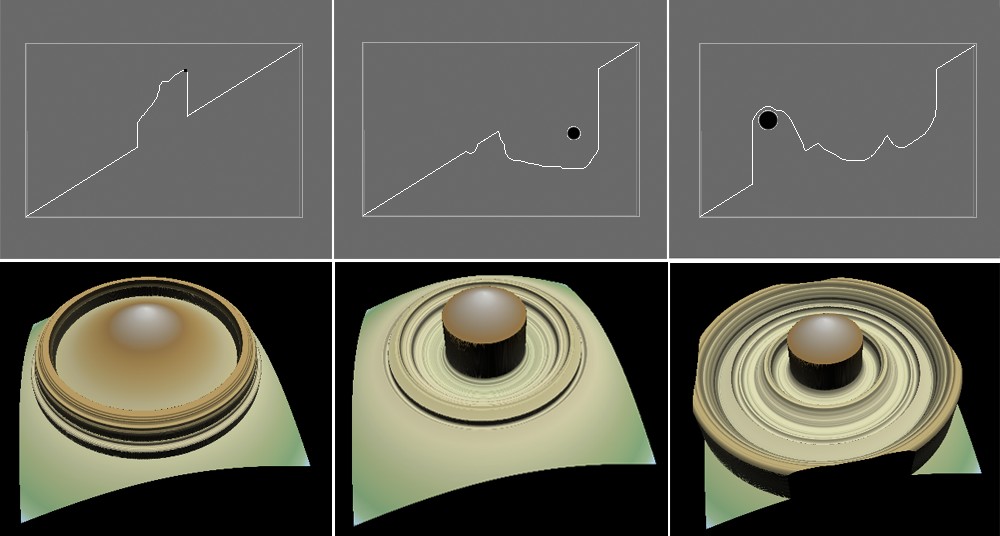
- Click and drag the mouse to change the circular symmetry values.
- Click OK to validate.
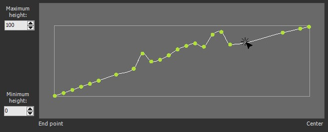
Smoothing the curve
Click on the Smooth button to smooth the values of a curve. You can click several times to smooth more.

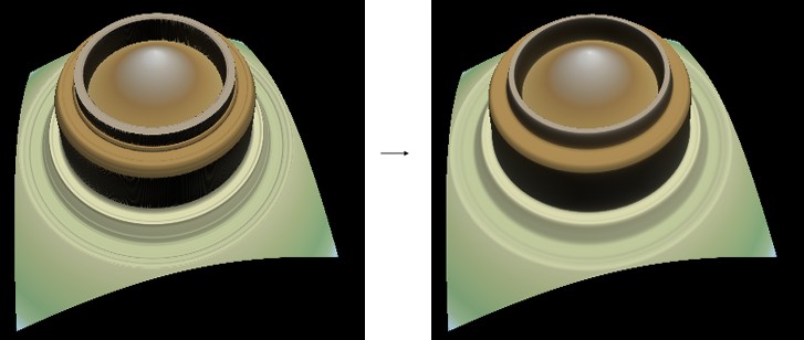 Smoothed
curve
Smoothed
curveAdding control points
Once you have edited your curve, you can switch from the Manual mode to the Point mode to add control points. The control points are displayed in increasing subdivisions of five, from 5 to 50 points. A higher number of control points gives you more control over the changes you make to the curve.
- Click on the Point button in the Parameters dialog.
- Select the maximum number of subdivisions from the drop-down list.
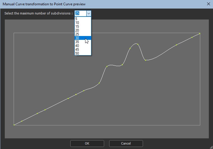
- Click OK to validate.
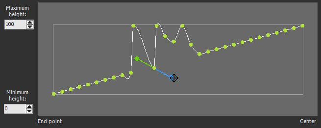
Editing a control point
The Automatic point editing option is selected by default. This option does not use anchor points:
- Edit the control points by clicking on a point and dragging the mouse to a new position.
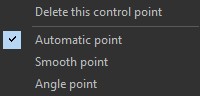
- To edit the curve using anchor points, right-click on a point
and select either:
- Smooth point: Drag the anchor points to smooth the point. The anchor points are paired, resulting in a smooth curve.
- Angle point: Drag the anchor points to smooth the curve. The anchor points are unpaired.
- Click OK to validate.
If you have not yet edited your curve in the Manual mode, you can click on the curve in the Point mode to add and edit points.
Deleting a control point
To delete a control point, right-click on it and select Delete this control point in the contextual menu.
Resetting the curve
Click on the Reset button to reset the curve to the default values.

Parameters
| Parameter | Use |
|---|---|
| Preset size | Select a preset size from the list to use pre-defined dimensions |
| Width | Width of the terrain to generate in number of vertices |
| Height | Height of the terrain to generate in number of vertices |
| Quad size | Size of the quads of the terrain in meters |
| Maximum height | Determines the height of the vertices whose value on the curve is 1 |
| Minimum height | Determines the height of the vertices whose value on the curve is 0 |

|
Smooth curve |

|
Changes the size of the brush used to edit the curve |

|
Returns to the initial curve (y == x) |

|
Toggles between the manual curve and the Point curve editing modes. |